
INNER KNOB - AF Knob -
The inner AF knob adjusts the receiver
audio volume levels of the internal or
external speaker. Clockwise rotation
increases volume level.
Outer Ring Knob -
RF/SQL knob
Rotate this knob counter-clockwise to reduce the
background noise and the system gain. Rotate this
knob fully clockwise to set the gain to the highest
level for normal operations. Counter-
clockwise rotation will raise the start position of
the S-Meter indication. When receiving a strong
signal, the noise is reduced and the signal is emphasized.
- Rotate this knob slightly counter-clockwise
to the point where the “stationary” meter
indication is set just about the same as the
receiver noise level.
This control may be changed to function
as the squelch control by selecting “SQL” on
Menu Mode “05-05 [RF/SQL VR]”.
MULTI function knob -
This knob incorporates multiple tasks and makes
it very convenient to operate the various
functions of the FT-891.
1 Adjusts the operating
frequency of VFO-A in 500 kHz Steps (except the for
AM and FM modes)
2 Adjusts the operating frequency of VFO-B
3 Operates the [A]/[B]/[C]/ [CLAR] key function
4 Selects the Desired memory channel
5 Switches the Setting Modes ON/OFF
6 Changes the Menu Mode setting values
[F] key - Repeatedly press this key momentarily
to step through the Setting Modes as follows:
➠ FUNCTION-1 ➠FUNCTION-2 ➠ CW SETTING ➠
Select the desired function from the Setting
Modes, and then press the MULTI
function knob to switch the selected function ON or OFF.
- While in the Setting Modes,
to assign the Setting Modes
to the [A]/[B]/[C] keys, rotate the
MULTI function knob to select the
desired function, and then press and hold
the [A]/[B]/[C] - FM SETTING, REC SETTING and ATAS SETTING
function screens may be enabled via Menu mode
“05-10”, “05-11” or “05-12”. - To return to normal operation, rotate the MAIN DIAL
or press another
Press and hold this key to activate the Menu mode.
● [A] (SFT): IF SHIFT function
In the SSB mode, IF SHIFT permits moving the DSP filter
passband higher or lower, without changing the pitch of the
incoming signal, and thus reduces or eliminates interference.
Press this key to display the IF SHIFT
- Rotate the MULTI function knob to the left or right to
reduce interfering sig - Press and hold the MULTI function knob to restore the IF
SHIFT setting to the factory default.
● [B] (SCP): The SCOPE function
The SCOPE function provides a spectrum display of the band
conditions. Press this key to display the band condition
(spectrum).
When the SCOPE function is active, the [A]/[B]/[C] keys are
automatically changed to the below operations.
[A](SPN) key: This key changes the displayed bandwidth.
Available selections are 750 kHz, 375 kHz, 150 kHz, 75 kHz, or
37.5 kHz ranges.
[B](SWP) key: Each time the [B](SWP) key is pressed, a new
scan of the spectrum scope is shown on the LCD display.
The SWP icon blinking on the LCD is confirmation that the
“Continuous Sweeping mode” is running.
[C] (NB): Noise Blanker function
The IF Noise Blanker can significantly reduce the noise that is
caused by automotive ignition systems.
[CLAR] key
During reception, press this key, and then rotate the MULTI
function knob to adjust the VFO-A RX clarifier offset value up
to ±9.998 kHz.
The clarifier offset value (frequency) can be restored to “0
(zero)” by pressing the MULTI function knob for more than one
second.
MAIN DIAL
This is the main tuning dial for the transceiver. Rotate this knob
clockwise to increase the operating frequency and rotate it
counterclockwise to decrease the operating frequency.
- Pressing the [FAST] key will change the tuning of the
MAIN DIAL to a higher step rate.The frequency steps
available are 10Hz and 100Hz per step (2kHz and 20kHz
per rotation).
Pressing the [PWR/LOCK] key briefly will engage or release
the DIAL knob lock.
[QMB] key
Press and hold this key for more than one second to write
the frequency and the data presently displayed on VFO-A
to the quick memory bank (QMB).
- Once all 5 QMB memories have data written on them, the
previous data will be over-written on a first-in, first-out
basis.
- 5 QMB memory channels are Press this key briefly to recall
the data written onto the quick memory banks (QMB) one
by one. - To change the frequency in the recalled quick memory
bank (QMB), rotate the MAIN DIAL.
[M▶V] key
This key will copy the saved data from a written memory
channel to VFO-A. Press this key to display the “MEMORY
CHANNEL” list screen.
Rotate the MULTI function knob to select the desired
previously written memory channel.
Press this key again to copy the currently selected memory
channel data to VFO-A.
[V▶M] key
This key is used to save the data from VFO-A to a memory
channel. Press this key to display the “MEMORY CHANNEL” list
screen.
Rotate the MULTI function knob to select the desired memory
channel.
Press this key again to copy the VFO-A operating data to the
selected memory channel.
- When the “MEMORY CHANNEL” list screen is displayed,
press the [A]/[B]/[C] key to edit the selected memory
channel.
[V/M] key
This key toggles frequency control between the VFO and the
memory systems.
- When the memory channel data is recalled, the previously
selected Memory channel
number is displayed like “M01”.
- Rotate the MULTI function knob to change the memory
channel - While operating on a memory channel, if the MAIN DIAL
knob is turned, the “Memory Channel Number” will be
replaced by the MEMORY TUNE indicator “MT ”; this
indicates that the operating frequency of the Memory
Channel is temporarily changed. Pressing the [V/M] key
while in the MEMORY TUNE state will restore the previous
memory channel data.
[A/B] key
Pressing this key momentarily, exchanges the frequency and
memory channel data of VFO-A and VFO-B.
Press and hold this key for one second to set VFO-A and VFO-B to
the same frequency and data values.
[BAND (MODE)] key
- Press this key to display the “BAND SELECT” screen
(Operating band selection screen). - Rotate the MAIN DIAL knob to select the desired frequency
band (operating band).
The selected frequency band will be set automatically in one
second and the display will return to normal operation.
Press and hold this key to display the “MODE SELECT”
Rotate the MAIN DIAL knob to select the radio modulation
form (operating mode).
The selected operating mode will be set automatically in one
second and the display will return to normal operation in the
selected operating mode. (The mode is automatically preset
for each operating band, it is only necessary to set “MODE SELECT”
when a change is desired).
[FAST] key
Press this key to change the tuning of the MAIN DIAL to a
higher step rate. The “FST ” will be displayed at the bottom right
corner of the screen.
The tuning steps for the MAIN DIAL knob are set at the factory
to 10 Hz -100 Hz for one step and 20 kHz for each dial rotation, in
the SSB/AM/CW/RTTY/DATA Mode (One kHz for each step and
200 kHz for each dial rotation in the FM Mode).
TX/BUSY Indicator
The Indicator glows green while the squelch opens on receiving
signals. The Indicator glows blue: While Zeroing during CW mode.
On receiving a signal with a CTCSS/DCS tone matching the
squelch tone code setting of the transceiver.
The Indicator glows red when transmit is engaged.
[PWR/LOCK] key
Press and hold this key to turn the transceiver ON or OFF.
Briefly press the key while the transceiver is ON to engage the
MAIN DIAL knob lock. This key toggles the MAIN DIAL knob lock
ON/OFF.
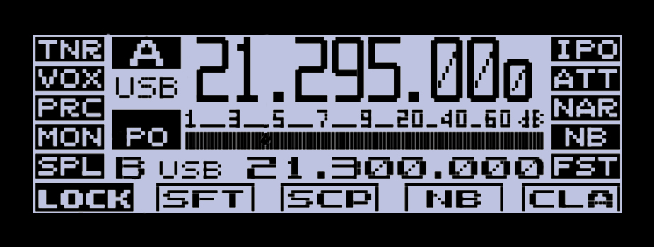
Antenna Tuner - Indicates
if a tuner is present.
The VOX function is in use
The Speech Processor
function is in use
The Monitor function is
in use
Running split operation
Lock Feature Active
Displays the various Operating Modes:
A/A VFO-A
M01 - Memory Channel Number
PMS - Programmable Memory Scanning
QMB - Operating with the Quick Memory Bank
MT - Memory Tune
EMG - Recalling the emergency contac tfrequency
Mode Indicator -
USB, LSB, CW, Etc...
Meters Indicator -
PO - Output Power Meter
ALC - ALC Voltage Meter
SWR - Standing Wave Ratio Meter
CMP - Speech Processor Compression level Meter
IDD - Displays the drain current of the final stage FET transistors
Actual Meter Reading based on
what you have showing on the left
Current Operating Frequency
VFO-B data Clarifier operation
VFO-B
Clarifier
The receiver preamplifier is OFF
The attenuator is in use |
The Narrow IF DSP filter is in use
The noise blanker is in use
MAIN DIAL at a higher step rate
IF SHIFT function
Scope Function
Noise Blanker Function